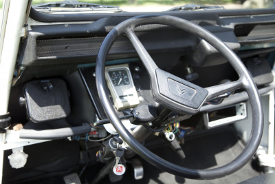
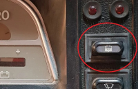
When the dashboard light fails or when the speedometer is almost invisible in the dark, it's time to replace the light.
It is important to know that the cable of the speedometer is attached to the dashboard. There are two ways to detach the cable from the speedometer. The first method is to disconnect the cable from the gearbox. To do this, both splash guards must be removed. Another method is to disassemble the battery and the battery box. This method is described here.
The battery and the battery box are disassembled and you immediately look through the hole on the back of the dashboard. You can easily unscrew the cable gland from the speedometer.

Then the screws can be removed from the dashboard. Two on the left and two on the right.

The third screw on the left side can remain in place. This means that the meter plate is fixed in the dashboard.

In the photo of the back of the counter plate, the socket of the light is circled in yellow. The light that belongs in it is a 12 Volt T4W 4 Watt light with a BA9s base/socket.

After replacing the bulb, everything can be reassembled in reverse order. Reconnecting the counter cable may require some patience. Loosening is done in no time, but securing it is sometimes more difficult. But the same goes if you have loosened the cable on the gearbox. Securing the meter cable to the gearbox does not always work in one go.
Amenities:
- Phillips screwdriver
- Stitch Ring Key 8, 10, and 11
- New light 12 Volt T4W 4 Watt bulb with a BA9s base/socket
- Patience
- Possibly socket 8 and socket 19 with ratchet to disassemble the mudguards if you want to disconnect the counter cable on the gearbox.
Right next to the discs are the brake pads. Replacing the brake pads seems more complicated than it is in practice. The cost is not either, so if there is any doubt about whether the brake pads are still good, it is advisable to replace them. My preference is for a renowned brand such as Brembo. The easiest way is to disassemble both side screens.

The closer the steel of the blocks gets to the discs, the thinner it will beis becoming the friction material. Don't wait for the steel to touch the discs. Also install new discsis more expensive. Always replace the blocks one by one, otherwise when pushing back the next block, the first one will bepiston is pushed back and you can never get a block in between without disassembling the brake calipers.

The new blocks are thicker and so the old block has to push the cylinder back first to make room. Push withA sturdy screwdriver pulls one of the blocks off the disc to the side. Until the thicker new blockin between.

Lift the retaining spring and the brake pad will fall down. Catch the old block. Otherwise, this falls exactly into the cooling tunnel underneath.
GodHold the new block in place as high as possible and pull it into place under the clamping spring. In the otherBlock the same way and then step on the brake pedal to push the cylinders.Do this before you ride! Otherwise, you won't have any brakes!The new blocks should be the firstTwo hundred kilometers should be used carefully to wear on the disc. Necessity, of course, breaks the law.
Amenities:
- Socket 8 and socket 19 with ratchet to disassemble the mudguards
- Two sturdy flat-head screwdrivers
From time to time, the valves need to be adjusted. It is necessary for the engine to function properly that the valves are properly adjusted.
On both sides of the engine block is a cylinder head with a total of four valves. Two exhaust valves and two intake valves. In particular, the exhaust valves have to deal with it. The red-hot gas mixture that has just been burned blows past it again and again at an enormous speed. The temperature of this combusted gas can rise to about 1000ºC. The valves are therefore constantly cooled with oil.Despite this, both the valves, the valve stems and the rocker arms get quite warm. However, warm materials expand and to prevent the valves from closing completely due to expansion, a small amount of space must be left between the rocker arm and the valve stem. Not too much, because then the valves won't open far enough, but certainly not too little, because then they won't be able to close properly.It seems so simple, a little space or play in between and then you're fine. But over the years, various engine types have been developed. The valves of all these types have to be adjusted periodically (every 10000km), but unfortunately not all in the same way. We will try to indicate as briefly as possible what differences there are and then only describe the adjustment of the valves of the .
Koud of warm?2CVs from before March 1954 are set with a cold engine, then until about 1973, with a warm engine. This meant that the car had to be driven for a while before adjusting the valves. The first mentioned adjustment when the engine is cold is 0.15 mm for the intake valves. and 0.20 mm. for the exhaust valves. If the adjustment has to be done for a warm engine (see the Citroën manual for this) then the clearance for both types of valves is 0.20 mm.
With the 2CV6 engines, the valves are adjusted at 20ºC outside temperature, with a cold engine. Both the inlet and exhaust valves are adjusted to 0.20 mm.This applies to modern 602cc engines.

Adjusting valves for a 2CV6 and similar engines with cooled engine:Place a small container (e.g. from the Chinese or an empty butter dish) under the valve cover, to collect the oil that is in the valve cover. It's just a little bit of oil, but if there's no container underneath, it makes a lot of mess.

After loosening the nut of this cover with wrench 12, it is sometimes necessary to give the cover a small tap with a plastic hammer to loosen it. We do the same on the other side.
There are three methods that can be used to adjust the valves. All three work equally well and it's up to you what you find easiest to work with.
Method 1: (Opposite Valves) The engine should be turned until one valve is fully opened on one side. Now adjust the same valve on the other cylinder. This procedure must be performed for each valve.
Method 2: (Same Side) One valve is fully open; The other valve on the same side needs to be adjusted. This procedure should also be performed for each valve.
Method 3: (balanced) On one side, both valves must be in the same position. The exhaust valve closes and the intake valve is just starting to open. When both valves are at the same height, adjust both valves on the other cylinder.
What I'm describing here is method 1.
We can make the engine run slowly by hand with the crank, or by lifting one front wheel just off the ground with a jack. When the gearbox is put in second gear, the wheel can be turned with little force and the engine rotates with it. Some people disassemble the spark plugs so that the engine runs more easily without resistance. Personally, I am not in favour of this, because something could always fall into it.
We then turn the engine around until we see one of the bottlenose dolphins go inside.

We stop turning and can now check the rocker arm of the opposite cylinder and adjust it if necessary.

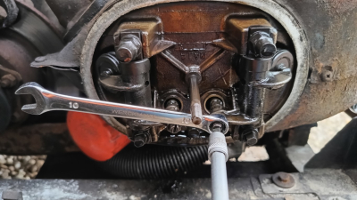
If a 0.20 mm feeler gauge can pass smoothly between the valve stem and the rocker arm, the valve is in the right position. If you hear a (soft) tap when you run a feeler gauge of 0.20mm through it, it is just not in the right position. What should definitely go smoothly through it is 0.15 mm. If 0.25 mm fits smoothly, the clearance must be adjusted to 0.20 mm.The easiest way to adjust this is with a special valve adjustment wrench. However, I can also do it with (ring) wrench 10 and a well-fitting screwdriver.

We check the other valves in exactly the same way by opening the same valve from the opposite cylinder.


Personally, I always err on the side of caution, and turn the engine around a few times and then measure again. After all four valves have been properly adjusted, the cover is reassembled. First, check the valve cover gasket. This one should still be flexible, you should be able to make an impression in it with your nail. Replace the gasket if it is too hard.

The valve cover gasket should be glued to the valve cover with Bostik 1400 Neoprene adhesive. If present, the widest part of the gasket should be at the bottom. The lid should only be tightened very lightly, 5-7 Nm if you have a torque wrench. In practice without a torque wrench, you can tighten the nut of the valve cover by hand and then half a turn extra with the wrench12 tighten until there is some tension on the lid. The lid must no longer be able to be moved back and forth by hand, otherwise the nut will have to be turned at most once. If you make more strokes, you run the risk of pulling out the stud when the engine warms up. After lightly tightening the covers, check if there is any oil leakage by running the engine. After this, check the oil level and top it up.
So in short:
Adjusting the valve: opposite valve of the other cylinder must be fully open.
For older engines, the following applies to:
Before March 1954: cold engine, 0.15mm intake, 0.20 exhaust valves. Check the manual on how to adjust it.
1954-1973: warm engine, both 0.20mm. Check the manual on how to adjust it.
0.20mm, inlet-an exhaust valve. Adjust with COLD engine.
Amenities:
- Krik of slinger
- Stitch key 10 and 12
- Flathead screwdriver ora special valve set wrench
- Feeler gauge kit with sizes 0.15, 0.20 and 0.25 mm
- Socket 8 and socket 19 with ratchet to disassemble the mudguards
A 2CV also needs regular maintenance. Good maintenance ensures a lot of safe kilometers and reduces the chance that you will come to a standstill. In addition, you will get to know your 2CV well.
The maintenance of course depends on the kilometers driven and is divided into four schemes that you can download for free at the bottom of this page. If no maintenance history is known, I recommend that you run the most comprehensive schedule: maintenance schedule D:
Service - Under the car
- 1) Motorcarter: draining
- 2) Oil filter (if fitted): replace
- 3) Gearbox/differential: draining
- 4) Doorsmeren (nippels): fusees (2), schuifstukken (2) van aandrijfassen – Total MULTIS
- 5) Spring system: lubricate tilting blades with oil
- 6) Brake lines: check
Service - Wheels and brakes
- 7) Disc brake pads: check
- 8) Brake lining for: check
- 9) Rear brake lining: check
- 10) Braking: adjusting
- 11) Handbrake: adjusting
- 12) Tyres: check condition and voltage – Cold: 125R15 – front: 1.5-1.8bar (21-26 p.s.i.), rear 1.8bar (26 p.s.i.); 135R15 – front: 1.4bar (20 p.s.i), rear 1.7bar (24 p.s.i.)
Service - Other activities
- 13) Motorcarter: refill, e.g. Total GTS 20W50. Capacity 2.2 litres
- 14) Gearbox/differential: refill – Total EP SAE 80, capacity 0.9 litres
- 16) Brake fluid reservoir: refill – Total Hydr. BRAKEFLUID HD, models with disc brakes only Total LHM
- 17) Speedometer cable: Lubricate with grease
- 18) Pedals: lubricate pivot points with oil
- 19) Coupling cable (disassembly and assembly): lubrication with grease – Total MULTIS
- 21) Fan belt: adjust, replace if necessary
- 22) Valves: adjustment – inlet/outlet (cold)
- 23) Spark plugs: cleaning, replacing and adjusting if necessary – distance electrodes 0.6-0.7mm
- 24) Breaker points: check, refresh and adjust if necessary – distance 0.40-0.45mm
- 25) Crankcase ventilation system: valve cleaning and checking
- 26) Air filter: replaced
- 27) Carburetor: cleaning filter and nozzles
- 28) Carburetor: lubricate rods with oil
- 29) Clutch: adjustment – freestyle pedal 20-25mm
- 30) Battery: refill, clean clamps and lubricate with Vaseline
- 31) Ignition: adjust time (see special factory instructions)
- 32) Carburetor: adjusting
- 33) Electrical installation: check
- 34) Headlamps: adjusting
- 35) Hinges, locks, door catchers, etc.: lubrication with oil
- 36) Windscreen washer reservoir: refill
- 37) Windscreen washer: check
- 38) Front wheels: alignment – track (untaxed) 1-3mm, camber 1° +/- 30
- 39) Fuel/oil: check for leakage
- 40) Take a test drive
Download your free maintenance schedule here:
You can get which schedule you need from the table below:
| Servicebeurt | Mileage | Servicebeurt | Mileage | |
| A | 5.000km | A | 105.000km | |
| B | 10.000km | B | 110.000km | |
| A | 15.000km | A | 115.000km | |
| C | 20.000km | D | 120.000km | |
| A | 25.000km | A | 125.000km | |
| B | 30.000km | B | 130.000km | |
| A | 35.000km | A | 135.000km | |
| D | 40.000km | C | 140.000km | |
| A | 45.000km | A | 145.000km | |
| B | 50.000km | B | 150.000km | |
| A | 55.000km | A | 155.000km | |
| C | 60.000km | D | 160.000km | |
| A | 65.000km | A | 165.000km | |
| B | 70.000km | B | 170.000km | |
| A | 75.000km | A | 175.000km | |
| D | 80.000km | C | 180.000km | |
| A | 85.000km | A | 185.000km | |
| B | 90.000km | B | 190.000km | |
| A | 95.000km | A | 195.000km | |
| C | 100.000km | D | 200.000km |
I wanted to lock the trunk the other day and I got the key in the lock, but turning around was not possible.
After injecting with WD40 and fiddling with the key, it eventually managed to turn the key around for a quarter. Pulling it out certainly didn't work. 
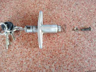
Then disassemble the lock and see if it's commonplace. I was surprised how much rubbish and dirt can get into such a lock! To remove the rust, I put all the parts in strong vinegar for over a day. Another acid will work, as long as it's an acid. This reacts with the rust and so you can easily remove the rust.
After the acid bath, rinse well under the tap and continue cleaning the lock. With me, the slide was fixed, but with some drenched and back and forth I got the slider common.

In this slide there is also a cap with a spring behind it. With me, this cap was stuck in the slider. To get it loose, I used a very thin drill to pierce a hole in the cap so I could pull it out.
Then clean thoroughly and close the hole with the soldering torch and some tin.
The whole lock is then put back together (don't forget the little feather) and it works as it is meant by Citroen.
What I've read on many forums is that you shouldn't put grease in the lock. Only graphite powder and I share that opinion. Probably the previous owner of my 2CV used grease for the lock.
When I first started a 2CV, I did this the way I started a modern car.
Turn the ignition key and continue starting until the engine continues to run.
However, this is not the way a 2CV should be started.
How do you do it?
With a cold engine we pull out the choke about halfway. Then we turn the key with the left hand, very short, 1 second is enough and then we release the key.
Often the engine already runs. If it hasn't been struck yet, the choke can be pressed or pulled out slightly, that's purely on feeling.
Even with a warm engine we turn the key very briefly, a touch of about 1 second is enough!
You have a French lump of metal in the workshop, you know it's a 2CV engine, but whether the thing is running or not can only be said with certainty if the machine is built into a duck and an attempt is made to start it. The frustration is great when the engine rattles and stutters after a long period of hard work or does not start at all. That can be fixed.
I built myself a device to test engines solo, outside of the duck. For this you first need a broken gear box, which is disassembled so that the front gearbox part falls off. This is equipped with a starter. With the starter screw connection, a battery ground cable is screwed in. When connecting the starter, an analog plus cable. A cable with a plug on the other side is screwed onto the connection screw of the positive cable for the battery to be inserted into the plus connection of the coil.
Now insert a coil with ignition cables on the plugs and cable on the motor from the crusher contact to the minus of the coil. With the motor starter described above, which is clamped to the magnetic switch on one side and the positive connection of the starter on the other, we can play with the ignition lock. The petrol hose is extended with a piece of new hose and put in a petrol can. An oil pressure control light is now very noble, which is simply connected between the cable on the motor and the plus to the starter. All these machines are now simply screwed onto the respective motor, two nuts are enough to test, one at the top right and one at the bottom left or vice versa...
Given that the engine has certainly been standing for a while, it makes sense to first flood the carburetor and the fuel pump with gasoline with the help of a syringe. And then see if the spark plugs are still there and under certain circumstances adjust or even renew the contacts and valves. Oh - oops - see if there's any oil left in the engine. Now connect a battery to the cable and ready. Put the battery and the petrol can in front of the engine, because the exhaust is practically the heat exchanger and the flames can be thrown out...
Before starting the engine for the first time, unscrew the motor from the coil with the positive cable and check for oil pressure, hence the oil pressure indicator light. If there is oil pressure, the machine can now be started online, i.e. with the plus connected to the coil. Makes a lot of noise, so don't necessarily keep this action on the Sunday before going to church. When the engine is running, check that both cylinders are running optimally. Once you can check this by holding your hands to the right and left of the exhaust (which is actually not there) and seeing if the pressure on both sides is the same (note: hot + possibly flames!).
If the machine has been running for a while, you can also test the parallelity of the heat on the heat exchangers and valve covers. If both sides are the same, these are good conditions for a good machine. The rattling of curlers or piston pins can also be heard in this riot, I have organized a stethoscope with a long stick. As a result, you can hear specifically defective crankshafts, piston pins or simply rattling valves to the sound. It is now also possible to test the compression of the machine in disassembled condition; You can't get real values with the pendulum.
It happens that the 2CV has to be started repeatedly to get the engine to work at all. This is the case, for example, when adjusting the contact or carburetor. If you then tinker with the 2CV, you will definitely have oily hands and use them to lubricate the door handle, the ignition key and the choke lever. Apart from that, the duck always goes out if you want to close the door and go to the engine. I came up with something very simple. Take a switch to test the brake fluid indicator light with two connected cables, about 30 cm long.
Put two crocodile clamps on it and that's all. One pole is connected to the plus on the battery, the other terminal to the thinner cable of the starter, the magnetic switch. Make sure all connections are insulated, otherwise you will get sparks. If you press the button now, you will do nothing but turn the ignition key without turning it. You can accelerate directly on the carburetor on the throttle and also the choke. Turn on the ignition, do not forget to pull out of gear and put on the handbrake. So you can start the engine and at the same time make any changes to the adjustment of the carburetor or the contact. If you are using a switch from another manufacturer, make sure that it is a button that interrupts contact immediately when it is released.
Even the emergency service is pretty stunned for a 2CV if the contact no longer does what it needs to or the V-string hangs in the fan housing. The 14 mm cap with 1/2' drive is sometimes too thick and does not fit in the propeller.
Many 2CV drivers therefore have a 14 mm pipe key with them in their on-board tools. However, for permanent use, the key available in regular stores is quite stupid. These things have holes to insert a screwdriver or something like that and act as a lever, but how often has a screwdriver broken off if the bolt is too tight? The remedy is a normal cap key size 18, which fits perfectly on a standard 14x15 pipe wrench on the 15 mm side. So you can unscrew the bolt safely and easily with a 1/2' drive or ratchet. Also looks great this tool...
You can also use a 19 mm ring wrench and the mentioned water pump pliers. Another option is to use a perfectly normal 14 mm cap with a 3/8' drive and extension, which is thin enough and fits depending on the manufacturer. I myself use a long cap from Facom with a 1/2" connection. This also makes the fan a bit wobbly and possibly loosening a little left and right. One never stops learning...
If the braking system needs to be vented after replacing the main brake cylinder, brake lines, calipers, rear brake cylinders or anything else, most keymen will use the tried and tested method and do so with a helper. One is in the duck and pumps the liquid through with the brake pedal and the other sits near the vent nipples of the brake lines or caliper. This method also works, but can put an end to the main brake cylinder, since the pedal is never fully kicked in during daily use. This unnatural movement of the main brake cylinder can lead to death, especially if the main brake cylinder has been under the belt for a few years. Besides, you always have to be together.
It's only possible, but I don't want to describe that here. Apart from that, this method does not work at all with a new main brake cylinder, because the main brake cylinder comes without brake fluid and even with a full tank it is almost impossible to get liquid into the main brake cylinder, so there is desperate pedal pedaling and air pumping with minimal brake fluid. Because I work 98.57% alone in my workshop, I came up with something.
One-man operation including main brake cylinder protection. In the magazine Oldtimer-Praxis, issue 6/97, remont airers were presented that actually all work according to the same principle. Enter compressed air into the system by means of a compressor or a fully inflated tyre. However, these devices do not have the right connection for the brake fluid reservoir of the 2CV, I do not have a compressed air connection in my workshop and these things also cost a lot of money. And as a half-seauw, I make my brain work to minimize costs.
So I put together my own machine. Due to the lack of a compressor or permanent compressed air connection, I have thought about where I can get the pressure. I grabbed a perfectly normal bike pump, organized about 2.5m plastic hose and an old cap for the brake fluid reservoir. I put a bicycle quick valve in the bicycle pump and fastened the hose with a hose clamp. I sawed off the floating chamber of the brake fluid reservoir and screwed in a vent nipple of a caliper instead of the float pen.
I attached the other end of the hose to the valve. Now there is another problem. The clogged part of the float cover is not airtight. I visually welded it with the help of a soldering iron. After that, it is very simple: unscrew the cap of the brake fluid reservoir and place the cap of the vent device on top. Then with the bicycle pump back to the rear brake cylinders, nipple open, hose on top with bucket to catch and pump the old brake fluid. It works excellently and you are at the site of the action and can bleed or vent the braking system yourself.
Completely change the brake fluid. When venting the braking system, it should be noted that starting at the furthest removed nipple calculated from the main brake cylinder, so that is one of the rear brake cylinders, right or left of the 2CV that is really irrelevant, I chose the right first, I do not know why, but already had problems when I started on the left. Might have something to do with the direction of rotation of the earth or the yogurt or something...
Then, wisely, at the front of the caliper, to the left of the vent valve, the same method. In the case of drum brakes logically with the two front brake cylinders.
More...
When adjusting the rear brake, some caution is required, as slipping with a ring wrench or ratchet with a jammed or round eccentric hexagon ensures that the brake line is in the immediate vicinity and easily damaged. Apart from that, you can no longer adjust the brakes with a round hexagon. The metrinch tools that have been available for some time and that also loosen round nuts or screws are actually almost standard in a well-equipped workshop.
These metrinch tools do not affect the hexagon on the corners, but rather on the flanks because of the waveform, and therefore this tool does not care much about a screwed nut. The disadvantage of the nuts is that they have a rounded shot and that the fairly flat-setting eccentric nuts of the rear brake do not grip well. I sharpened the rounding of a 14 mm metrinch nut so far that the nut has no chance of sliding off, even with a round hexagon.
I did the same with a normal 17-nut. This means that the front axle bolts are tightened when this typical crack occurs when starting and braking. If necessary, press the tool against the screw with a mobile jack to prevent slipping. The roller jack with turntable is perfectly suited for this. Wheel hub puller Special tools are required to remove the wheel hub. It is actually just a thick thorn with the following dimensions:

With this part and a heavy hammer you can knock out the wheel hub. This is necessary if the wheel hub is damaged and needs to be replaced, and especially when replacing the wheel bearings.
Special tools are required to adjust or remove the track rod end. Sooner or later, the hammer and screwdriver method will destroy the internal thread of the track rod end and the screw. I made something out of a 1/2' nut. I've bent the nut so that only the holder for the ratchet remains. Then I welded a cross of 3 mm thick metal strips, which fits exactly in the adjusting screw of the rail end. Now you can unscrew the screw or make the adjustment with feeling.
The carburetor of the 2CV is screwed onto the manifold with four M8 / SW 12 nuts. The rear nuts are easy to reach with a normal ring wrench. This is not the case with the front nuts, which can only be reached with a normal key after removing the oil filling opening. But the oil filling opening can only be loosened with a long T-key SW 11 or a ratchet with extension, apart from the tricky reinstallation.
So the two front nuts are crying out for a special tool. For this I bent a 12 mm ring wrench at right angles in a vice so that about 3 cm from the ring to the bend. Then the end of the fork is deflected and a T-handle is welded from a tube with a diameter of about 1-1.5 cm. This is an excellent way to get to the hidden notes.
I made the same of the forked fork end, because sometimes the ring wrench does not work, because some specialists have tightened the nut with a hammer and chisel, partially smashing the hexagon. It is important that only the nuts SW 12 are used, since the space for the key is already tight. If a nut SW 13 is felted on it for reasons of replacement, one feels really sad when screwing and tightening the nut.
The steering column, which must be removed or removed when changing frames, removing front axles or pointing two-spoke steering wheels, usually has a very strong connection to the steering round. To do this, first remove the steering wheel cover and tilt the rust remover in the steering column and let it act. The steering column clamp (SW 11) is best loosened after the Ko-t wing has been removed. Remove the screw and use a screwdriver to pry the clamp open so that it falls down.
Now the locking ring must be removed from the steering lock. To do this, unscrew the cover around the locking ring (SW 7) and unlock the steering lock. Now turn the handlebars and dive into the duck's foot space and look from the back right into the opening of the steering lock. There you can see the locking ring, which is attached with two allen bolts SW 5. Unscrew the screws until the locking ring can be pressed onto the column. It makes sense to remove the flashing light relay, because that's a bit in the way.
Now all that needs to be removed is the steering column. Sometimes it is enough to pull the steering column at the bottom of the steering wheel spoke with more or less powerful handshakes. However, if the steering column is still there with the original rust since 1986, another method should be used. Variants with distribution forks, chisels or screwdrivers at the bottom of the rumdöllern steering column usually lead to their death. If the steering column is already broken or the tooth is turning, it does not matter, but care must be taken that the toothing of the steering round is not crumbled if it is not already over...
If the steering column is to survive, a tractor must be used. My construction for this looks like this: Take an old handlebar and remove the foam rubber in the middle, where it is screwed onto the steering column. Now bend this centre piece loose and read an M 12 nut on the top. Make sure that the nut is exactly flat on the middle part. The nut must then be machined with the flex so that all three screws of the steering wheel attachment can be screwed onto the steering column. If necessary, work with allen bolts.
Now turn an M 12 wire rod, which is about 50 mm longer than the steering column, through the welded nut and weld another nut to it. To pull off the steering column, remove the handlebar, insert the trigger into the steering column and secure it with the three SW 11 screws. Now turn the wire rod into the steering column with a 19 mm spanner until it gets to the steering round of the front axle. As you continue to rotate, the steering column is now carefully pulled through the curve. Voila!
Before mounting the steering column, check that the tooth is still in order, that the steering column has a crack (usually at the level of the cutout for the steering column screw) or is even bent. When replacing, do not forget the locking ring, the cover of the ignition lock and the rubber on the pedal base. It is best to replace the steering column clamp. When driving in the steering column, it is best to work together. The pillar is slowly lowered from the inside, the second holds the clamp around the pillar and slowly steers the steering column into place. The cutout of the curve should be exactly in line with that of the steering column, otherwise you will be sad when trying to mount the screw. Very important: always use a new screw (size M7 x 50 mm), self-locking nut and rings 7x14!
The position of the steering wheel spoke must of course also be taken into account when mounting. With the single spoke steering wheel, the spoke is logically nicely parallel at eight o'clock, with two-spoke steering wheels. After sliding the steering column open on two-spoke steering wheels, do not screw everything together, but check the middle position of the steering wheel by briefly and carefully driving in a straight line and possibly shifting the steering column again. Precise alignment greatly increases the entertainment value of a two-spoke handlebar.


